by P. Bizenberger, Jan. '01
with help from D. Thompson
Version. 2.4

by P. Bizenberger, Jan. '01
with help from D. Thompson
Version. 2.4

This manual introduces to the Graphical User Interface (GUI) that controls the following cameras:
It contains a full description of the software and the prepared options that will make observer's life much easier. For more information about the cameras, observing guidelines and general hints, see the home pages of the instruments.Although the GUI is an important step to get nice data in a convenient way, you still need a little bit of
Software development and maintenance: Christoph Birk and Clemens Storz.
Since this manual describes the GUI for all four cameras the displayed images here in the manual may look slightly different to the windows you can see on your screen when you actually run one of the cameras. The contents of the windows are arranged according to the selected camera e.g. if you have selected OMEGA Cass, the camera control panel shows a pull down menu for the grism wheel. Because in the other cameras are no grism wheels, the control panels for these cameras do not include this menu. All options for all cameras are described here, even if they are not shown in the image. So, you can find options here in the manual which are not used for the camera you are interested in.
To control the GUI is pretty easy, nevertheless you
should know how to talk to the GUI. There are three ways to give input
to the GUI.
The first is typing in parameters or commands using
the keyboard after selecting the appropriate box. These boxes are white
with a black frame and the current setting is written in the box.

If you move the cursor in the box the frame will
turn green. You can start to write the input and the background of the
box will turn red. In some boxes you can edit the old contents and in some
boxes the old contents of the box will be overwritten. Don't forget to
press RETURN after you finished your input. The background must turn to
white again.
The second way is to select a pop up (these ones
with the circle) or pull down menu (these ones with the triangle) with
the left hand mouse button. You have to simultaneously press the button
and move the pointer to the desired choice.

or

The third and easiest way to give an input is to simply click on a button (these with the shadow). The GUI will immediately start the appropriate process.

The GUI consists of seven windows:
A possible setup could look like this:
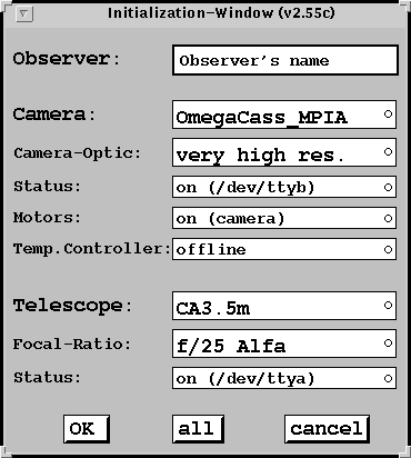
The Xterminal in which you started the GUI will be the interpreter terminal for the GUI. It can't be used as a normal Xterminal anymore. All messages from the software system will be displayed in this window and any command can also be typed in with the keyboard. See the macro list for the syntax of the commands.
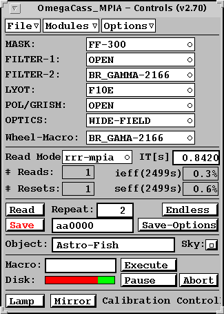
File Menu
Read Mode The different read modes available in various cameras are described in detail in the corresponding observer's manual. For standard broad band observing this should normally be left at double correlated read (called dcr or rrr).
IT(s) is the integration time in seconds. Note that the minimum exposure time with Omega-Prime is 0.8 seconds! Keep this in mind when doing broad band observations under high background conditions or when observing bright objects - the array can easily saturate during this 0.8 seconds of "dead time" while the array is resetting.
Repeat is the number of images with the specified exposure time which will be taken each time a read is executed. The total exposure time will then be N repeats times T seconds. The maximum number of images depends of the current setup of the computer with memory.
File Name The next file to be saved is given the name which appears in the window just below repeats. The name will automatically increment by one each time a save is executed.
Read The read button executes a read using the current exposure time and number of repeats. On completion of a read, the images are not saved unless autosave is selected under the save option.
Save The save button saves the most recent image(s) obtained using the currently defined save options.
Save-Options Calls up a save configuration panel which defines the default way in which to save images. The main choices are whether to save individual exposures as separate disk files, or to integrate them (sum) and save only a single disk file. Note that, as with MAGIC, the first image typically has problems. If saving integrated images, it is highly recommended that the first exposure of a series is not included in the sum! Also, note that the save options are overridden by any options specified in observing macros. For example "save -f 2 -i" in a macro will integrate from image 2 to the end of the series, and save only a single file, even if the save options specify saving images separately. Turning on auto-save will execute a save after every read, without clicking on the save button.
Endless turns on a continuous read. The images are read out with the current integration time and dumped to the display, but are not saved. This is useful for positioning the telescope before e.g. starting a macro.
Object is the object name which is written into the fits header under the keyword "OBJECT" for the current image. It will be updated automatically if object selection is done through object files (recommended), or can be changed by hand.
Sky Clicking on the sky button writes a sky flag into the fits header, but otherwise has no effect.
Macro Here, you specify a macro to read into the macro buffer. The filename, without the .mac extension, is all that is necessary (all macros must have the .mac extension). The macro file must be in the MACROS directory specified under the macro path on the options menu (see above). See also section 11 Macro Format.
Execute, Pause, and Abort control the execution of observing macros. Note that if a pause is issued, the macro will continue executing until the current command are completed! Check in the command window to be sure that the pause is in effect. Clicking on continue will continue executing the macro after the pause. This is useful when changing the dome slit segments.
Disk The green portion of the bar indicates the fraction of the selected disk space which is still available. If you are taking lots of data, keep an eye on this. The GUI also issues an audible warning when the disk is getting close to full (assuming you have not turned off the sounds!).
Lamp switchs the calibration lamp on or off (only for Omega Cass).
Mirror moves the mirror of the calibration unit in out of the beam (only for Omega Cass).
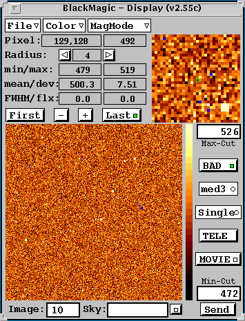
File Menu selects the basic display size.
Radius Sets the radius of the small cursor box on the image display. See the above note on FWHM-log about measuring the seeing.
min/max Show the minimum and maximum values of the pixels within the cursor box.
mean/dev Shows the mean and standard deviation of the pixels within the cursor box.
FWHM/flx Shows the FWHM and total flux (in counts) of an object selected with the cursor box.
First - + Last Controls the display of a series of images. Unless you need to review a set of images to determine, for example, whether the seeing was good enough to bother saving the data, just leave this on last.
BAD Toggles between displaying the bad pixels (in red) or not. Note that the bad pixels are ignored when determining display cuts only if the bad pixels are turned on.
Cuts Display stretch control. This button brings up a menu with various options for determining the minimum and maximum display levels. The options include:
Single/Sum/Ave Single will display each individual read as it comes off the camera. Sum will display the sum of all images taken in the current series. Average displays the average of all images taken in the current series.
Tele Provides for offsetting the telescope directly from the image display, which is useful for centering standard stars or science objects. Click on the "tele" button to get a green circle. Place this circle on some object on the display and click again. Move the cross which appears to where you want this object to be moved.
Movie Plays a movie of the series of exposures currently in memory.
Image shows which image in a series of repeated exposures that is currently being displayed.
Sky The "sky" button (small square) tells the computer to subtract a sky frame from the images before displaying, and is on when the square appears green. The file used for the sky frame is specified by name in the window to the left of the button.
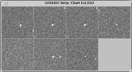
Send Send the current image to the data base of the strip chart.
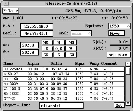
File Menu:
Relative offsets Offsets in arcseconds can be supplied in the dx and dy windows. Clicking on one of the directional buttons in the compass panel will then offset the telescope by the requested amount. The "set zero" button zeroes the cumulative offsets (S(dx) and S(dy)), and the "0,0" button in the center of the compass returns the telescope to this defined zero position.
Object Files An object file can be given in the Object-List window (the .obj extension is not necessary). Objects can be selected with a single click, and set with the set button. Setting an object sends the object's coordinates to the RA and Dec windows. These can then be sent to the telescope computer by clicking on move as described above. A useful feature is that when an object is set, the airmass panel will display the object's current airmass in graphical form, though there is no obligation to actually move to the object. See also section 12 Object List Format.
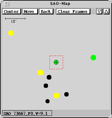
Stars can be selected by clicking on the image, with additional information (SAO number, spectral type, and visual magnitude) appearing at the bottom of the window. The coordinates can be sent to the telescope computer with the Move button.
A log of all previous exposures is kept, displayed as green squares on the SAO map. This feature is useful for following the progress of observing macros. Clear Frames will clear the display of the old frames, though future frames will continue to be displayed.
The SAOmap can be turned off by reselecting the "SAO map" option in the file menu of the telescope control panel. Using the "quit" option in the xwindows menu will also kill the telescope control panel!
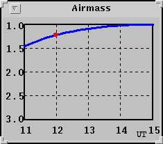
The airmass window can be turned off by reselecting the "Airmass" option in the file menu of the telescope control panel. Using the "quit" option in the xwindows menu will also kill the telescope control panel!
File
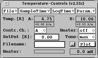
Enables or disables an acoustic warning for a temperature change. You
can select either an indication of a temperature change only to higher
temperatures or to higher and lower temperatures. Useful to check the running
out of helium.
Quits the window
SampleTime
Gives you a selection of values in seconds how often the Temp. display
is updated.
LogTime
Gives you a selection of values how often the temperature is saved
to the file. This value is always >= the value of the SampleTime
Param.
Here you can change the parameters of the PID controller. The default
values are the best for the MAX camera.
You can set the limits of the temp. and time axis for the plot.
Example:
| read | ;start the 1st read |
| sync | ;wait until all previous commands are finished |
| tele rel 25 25 | ;move the telescope |
| save -i -f 2 | ;save the data as integrated, starting from the second frame |
| sync tele | ;wait until only telescope move is finished, save will continue |
| read | ;start the 2nd read |
| sync | ;wait until all previous commands are finished |
| tele rel -50 0 | |
| save -i -f 2 | |
| sync tele | |
| read | |
| sync | |
| tele rel 0 -50 | |
| save -i -f 2 | |
| sync tele | |
| read | |
| sync | |
| tele rel 50 0 | |
| save -i -f 2 | |
| sync tele | |
| read | |
| sync | |
| tele rel -25 25 | |
| save -i -f 2 | |
| sync tele |
A complete description of the macro commands
is available as an HTML document.
Double buffering
It takes a considerable amount of time to transfer the data from the
camera and save it to the hard-drive on the workstation. To reclaim some
of this otherwise lost time, Omega-prime has been configured with two image
buffers. Thus, a new image can be read out while the previous image is
being saved. To implement this feature, the macros should be written as
in the example above, with a sync tele after the telescope offset and save
commands. The GUI will then only wait until the telescope move is completed
before starting the next read (the save command may still be in progress).
When observing in the K band, the increase in efficiency of observing (the
fraction of time spent actually integrating on source) is significant.
With 3 second integrations, 11 repeats, and saving images 2 through 11
as an integrated image, efficiency jumps from 33% to 40%.
Object name | Alpha | Delta | Equinox | pm.A | pm.D | mag | Comment
Example:
HD 225023| 0:00:11.8| 35:32:14.0|1950|0.0000|-0.004|6.96|J=7.97
G158-27| 0:04:12.0|-7:47:54.0|1950|-0.056|-1.85|7.43|J=9.31
HD 1160| 0:13:23.1| 3:58:24.0|1950|0.006|-0.013|7.04|J=7.06
HD 3029| 0:31:02.3| 20:09:30.0|1950|-0.0001|0.011|7.09|J=7.25
Gl 105.5| 2:38:07.6| 0:58:57.0|1950|*|*|*|*
HD 18881| 3:00:20.5| 38:12:53.0|1950|0.0001|-0.030|7.14|J=7.12
G77-31| 3:10:40.5| 4:35:12.0|1950|0.112|0.15|7.84|J=8.74
HD 22686| 3:36:18.7| 2:36:07.0|1950|0.0017|-0.010|7.19|J=7.20
HD 40335| 5:55:37.6| 1:51:09.0|1950|-0.0005|-0.018|6.45|J=6.54
HD 44612| 6:21:09.7| 43:34:35.0|1950|*|*|*|*
Note! The line | character is used as a separator between fields.
If you don't want to put in numbers in some fields, you still have
to use a * character as a place holder.
Important! If you have negative declination less than one degree than you must place the negative sign before the minutes e.g. 0:-13:45.6
The required fields are: Name, Alpha, Delta, Equinox
The optional fields are: pm.A, pm.D, mag, Comment
pm.A and pm.D are in units of arcsec/century.
All object list files must have the extension: *.obj
If you have any trouble with one of the instruments please report to Peter Bizenberger. We will create a list of problems (and if possible with solutions) to help future observers avoiding the same trouble.
Problem:
You can't start the GUI
Solution:
Type cleanup before you start the GUI. This program deletes
all remaining software parts from a previous session.
Problem:
Data is useless (counts between 0 and 65000, randomly distributed)
and the Abort button does not work.
Solution:
The fibers are connected wrong. Interchange the two fibers for the
data.
Problem:
Anything seems to work well but there are no stars.
Solution:
1. Check to see if the TV Guider mirror is in the optical path, if
it is, retract it.
2. Check the last button in the display window.
Problem:
Message 'can't allocate info page' and you can't start the GUI
Solution:
There is still a shared memory socket existing. Delete in the tmp
directory the shmsocket.
Peter Bizenberger
biz@mpia-hd.mpg.de
Tel. (+49) 6221 528311